When someone contacts me for Fluid Power Training, their first priority is how to troubleshoot their hydraulic systems.
 Unfortunately, from my 35 years experience, its not that easy, to be proficient at troubleshooting they first need to understand the basic function of Fluid Power components. For my customers who ask me for troubleshooting help, my first question, do you have a schematic? Without a schematic it is extremely difficult if not impossible (large manifold with slip-in cartridges) to determine first and second steps in the troubleshooting process. That is why I recommend, rather then teaching a troubleshooting class, why not incorporate troubleshooting, while teaching the identification of symbols and the basic function of each component in a hydraulic system.
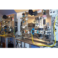
Once my students get comfortable with symbols and components, which takes about 2 days, itts time to put circuits on a hydraulic training simulator. I let the students put a circuit (maybe a sequence valve and pressure reducing valve simulating press and drill circuit), that I have drawn on a erasable board, onto one of my Hydraulic Trainers, and then let the fun begin.
As so often happens, the training mimics real life troubleshooting situations. The first thing that typically happens is the students who work together is teams of 4 start connecting hoses, and usually they over connect and do not pay attention to the schematic. This goes on for a while until I help them focus on the schematic as compared to the connections on the valves. Once the students realize that everyone has moved the hoses many times and still the system doesnnt work, they finally go through a systematic approach and verify that all the hose connections are in correct placement.
Now back to trouble shooting, the students who have verified the circuit is connected properly, panic because the circuit still doesnnt work. This is where the understanding of the circuit is handy, since they have placed two pressure valves in the circuit it is necessary to adjust them to the circuit drawings pressure settings. And they soon find out that it is necessary to have a lot of gauges and a flow meter is nice to. And some valves like SUN Mfg. adjust pressure higher by turning them counter-clockwise versus what you normally would think clockwise. So troubleshooting a system has to be done in a systematic approach while following pressure settings dictated by original designer. This is no different then replacing pressure relief, sequence, counterbalance, reducing valves on hydraulic systems in the field. Once they are replaced they also have to be adjusted back to original design specifications.
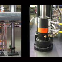
Hydraulic Trainer Equipment
I might add that pressure valves, such as sequence, counterbalance, relief, braking valve, look very similar as a symbol. What determines which valve it is, is often determined by where it is in a circuit and how it is being used. For further information on training FluidPowerTraining.net
|
|
Altair ProductDesign Unveils the Worlds First Series Hydraulic Hybrid Transit Bus
 BUSolutions LCO-140H to revitalize urban transit by increasing fuel economy by 110 percent and reducing 12-year fleet operations cost by $50 million for the average sized transit authority
Altair ProductDesign, a global product development consultancy and wholly-owned subsidiary of Altair Engineering, Inc., today unveiled the worldds first series hydraulic hybrid transit bus. The LCO-140H (Low-Cost of Ownership-1st 40-foot Hybrid) was developed under the BUSolutions program in partnership with Automation Alley, in an effort to revitalize public bus transportation in America.
Compared to the database of buses tested at Altoona, where the Federal Transit Administration (FTA) certification program is conducted, the LCO-140H fuel economy results are 110 percent better than conventional diesel buses and 30 percent better than the leading diesel-electric hybrid buses available today. The LCO-140 achieved an industry high fuel economy of 6.9 mpg when tested using the downtown stop-and-goo duty cycles and test protocol established by the FTA for transit bus certification testing.
BUSolutions is projected to lower the cost of ownership by $170,000 per bus as compared to a conventional diesel bus. With the average local transit authority operating approximately 300 buses, the savings could reduce a cityys cost of transit bus operation by approximately $50 million. When compared to an estimated $27 million increase in operational costs for a similar electric hybrid fleet, it is clear the LCO-140H could revolutionize the transit industry by providing reduced fuel consumption and emissions while improving the fiscal performance of a regional transit authority.
BUSolutions has been a collaborative effort between public and private entities to research, develop and commercialize advanced transit bus systems that are significantly more fuel efficient, have lower operating and maintenance costs, are competitively priced and can operate without updating the infrastructure of existing transit authorities.
In addition to investments by Altair and Automation Alley, BUSolutions has been funded by multiple federal and state programs including the FTA and the Michigan Economic Development Corporation (MEDC). It also has received exceptional local support by southeast Michigan congressional members, transportation industry partners, and local transit authorities SMART and the Detroit Department of Transportation (DDOT).
This project has been a collaborative effort from start to finish throughout the development, design and test phases. We would not have exceeded the goals we had set for ourselves had we not applied our knowledge and unique technologies to produce this revolutionary bus,, said Mike Heskitt, chief operating officer at Altair ProductDesign. BUSolutions demonstrates Altairrs expertise and capabilities as a concept-to-release, full vehicle development partner..
We are thrilled to have partnered in the BUSolutions program that is putting Michigan at the forefront of solving emerging public transit technology issues through innovation and collaboration,, said Ken Rogers, executive director at Automation Alley. Goals were set when this program started to produce a transit bus that was more fuel efficient, more affordable and more cost effective to operate for city transit authorities, and this project has both met and exceeded those goals..
Additionally, BUSolutions strategically partnered with regional and global high-tech manufacturers that assisted in incorporating state-of-the-art components and technologies from the transportation sector. Program sponsors include Parker and Meritor, which contributed significant driveline systems and knowledge. Various levels of support have been provided by PRAN, Sika Corporation, Meritor Wabco, Alcoa Wheel Products, Carrier Corporation, LADD Industries, Haldex, Shaw Development, Tenneco, USSC Group, Cummins Bridgeway, Multicolor Specialties and Williams Controls.
Altair has worked closely with local transit authorities, SMART and DDOT, to ensure the newly designed bus platform will meet regulatory requirements and address the needs of bus drivers and riders. Altair also established the BUSolutions Advisory Board to offer insight into broader community needs, as well as perspective on actual ridership issues and public-interface ergonomics. As a result, Altair ProductDesign successfully engineered the bus to incorporate design principles that will enhance the rider experience.
The LCO-140H Bus will also be demonstrated at the American Public Transportation Association (APTA) Expo in New Orleans Oct. 3-5 at booth #2281. For more information, visit the Altair events website.
About BUSolutions
Launched in 2005, the Altair BUSolutions program was established to develop and commercialize an advanced bus platform that lowers the total cost of ownership and environmental impact of commercial buses without updating the infrastructure of existing transit authorities. Leveraging the companyys deep domain knowledge in vehicle systems and cutting-edge, simulation-driven design practices to develop the design, Altair successfully partnered with Automation Alley, Michiganns largest technology business association, to secure federal funding to build working technology demonstrators for future commercialization. For more information, visit www.altairbusolutions.com.
About Altair ProductDesign
Altair ProductDesign is a global, multi-disciplinary product development consultancy of more than 500 designers, engineers, scientists, and creative thinkers. As a wholly owned subsidiary of Altair Engineering, Inc. (www.altair.com), this organization is best known for its leadership in combining its engineering expertise with computer aided engineering (CAE) technology to deliver innovation and automate processes. Altair ProductDesign firmly advocates a user-centered, team-based design approach, and utilizes proprietary simulation and optimization technologies (i.e., Altair HyperWorks) to help clients bring innovative, profitable products to market faster. To learn more, please visit www.altairproductdesign.com.
|
|
CONEXPO-CON/AGG & IFPE 2011 are a resounding success
 The mood was overwhelmingly positive at the CONEXPO-CON/AGG and IFPE 2011 expositions held March 22-26 in Las Vegas. Despite continued uncertainty in U.S. construction markets and the overall economy, industry professionals expressed hopeful optimism for a sustained U.S. upturn in the coming months, while global sales continue to be strong.
CONEXPO-CON/AGG and IFPE 2011 attracted nearly 120,000 registered attendees; the shows were the global industry gathering place for the year and the largest gathering in North America since 2008 for the construction, construction materials and fluid power/power transmission/motion control industries. The shows were held at the Las Vegas Convention Center.
Attendees said they were at the shows to examine the newest equipment and product technologies and innovations to help them prepare for future business; exhibitors cited the high quality of customers and reported strong purchases and sales leads to new as well as existing customers.
"The construction industry has been through some very tough times, with record unemployment, since the last CONEXPO-CON/AGG and IFPE in March 2008. With these positive numbers and the industry support of the shows, weere optimistic about the future and looking forward to seeing these new sales orders fulfilled," stated Megan Tanel, AEM vice president of exhibitions and events.
"There was such a tremendous upbeat feeling at the shows; it was really great to see our industry looking ahead with some enthusiasm after the recession," stated Mike Haberman, chairman of the CONEXPO-CON/AGG 2011 management committee and president of Gradall Industries.
A record number of more than 860 co-located events, educational programs and pre-planned meetings were held with the shows, plus dozens more meetings scheduled onsite. Co-locations included ICON Expo for the concrete products industry and several annual conferences of national industry associations.
Quality Attendance, International Scope
International registrations accounted for a record 24 percent of the total, representing more than 150 countries. CONEXPO-CON/AGG 2011 and IFPE 2011 were among a select group invited to participate in the U.S. Department of Commerce International Buyer Program, which facilitates the participation of international visitors. The shows hosted 42 official international customer delegations from 37 countries, organized by the U.S. Department of Commerce as well as in-country associations and related groups.
The majority of show attendees were key company decision-makers, including 44 percent with the top titles of president/owner and vice president/general manager/chief financial officer.
"The increased global participation by attendees and exhibitors underscores the importance of world markets to our industry. The U.S. economy is slowly improving and we have a ways to go, especially in construction, but after 18 to 24 months there is more pent-up demand for equipment to be ready for the upturn," Tanel stated.
"IFPE-related markets have fared somewhat better than construction and there definitely was a lot of positive momentum and interaction on the show floor. At both shows, attendees told us this was the place they needed to be to check out whatts new and get up to speed on the latest industry trends," stated Melissa Magestro, IFPE Show Director.
On the Show Floor
Altogether on the show floor there were more than 2,400 exhibitors taking more than 2.34 million net square feet of exhibit space. IFPE was the largest ever, and CONEXPO-CON/AGGGs exhibit space was the second largest in the showws history.
Reinforcing the global scope of the shows were 10 international exhibit pavilions - IFPE with pavilions from China, Italy and Taiwan, and CONEXPO-CON/AGG with pavilions from China, Finland, Germany, Italy, Korea, Spain and United Kingdom.
IFPE 2011 featured exhibit pavilions from the American Gear Manufacturers Association (AGMA) and the Power Transmission Distributors Association (PTDA), as well as an exhibit pavilion which highlights the expanded presence of sensors manufacturers at the show. CONEXPO-CON/AGG 2011 featured the IT & Business Solutions pavilion, sponsored by the Associated General Contractors of America.
Educational Opportunities
Industry-focused education was an important component of the show experience, and there were a record number of education, training and certification programs offered.
CONEXPO-CON/AGGGs education program featured a record 126 sessions across nine tracks, with sessions emphasizing industry issues and trends, management and applied technology, and numerous industry training and certification programs were also held. New for 2011 were a Crane and Rigging Conference and the Green Roads Summit.
At IFPE 2011, the 52nd National Conference on Fluid Power featured a record 114 presentations, and the Innovations Theater offered 14 sessions developed from abstract submissions for the conference. New for 2011 were national conference keynote presentations from leading industry and university researchers, and sessions from the Center for Compact and Efficient Fluid Power. IFPE also offered new college-level courses.
More than 80 allied associations and groups were official show supporting organizations, coming from the U.S., Canada and more than a dozen countries worldwide. They promoted the showss value and brought qualified buyer groups to the events, and many helped develop direction and content of the showss education programs to ensure they met industry needs.
Safety, Training, Workforce Initiatives
A Lift Safety Zone focused on cranes and other aerial lift equipment and ensuring adequate ground support for the machine and load carried. In conjunction with the Crane and Rigging Conference, a Crane Rodeo promoted education and safety at the same time as providing a hands-on operational experience. These and the many certification and training programs held at the shows helped ensure a properly trained workforce of equipment operators and other jobsite personnel.
The International Mixer Driver Championship by NRMCA recognized driver skills and inspection expertise. The AEM teen-focused Construction Challenge competition presented by Volvo Construction Equipment generated interest in construction careers. The I Make America national grassroots campaign had a substantial presence to promote job-creation policies for manufacturing and construction that improve the economy and keep the U.S. globally competitive.
VIP Guests
The shows welcomed visits from U.S. Secretary of Transportation Ray LaHood as well as U.S. Department of Commerce Assistant Secretary Suresh Kumar and numerous other government officials.
Looking Ahead
The next edition of the triennial CONEXPO-CON/AGG and IFPE expositions will be held in 2014 (March 18-22) at the Las Vegas Convention Center in Las Vegas USA
|
|
Modified valve from Continental Hydraulics Helps Waterjet System Unclog Containment Dome
 (Minneapolis, Minn.) There is no question the BP oil leak crisis takes engineering, thought and industry best practices. Intervention is rough according to James Miletich of Oceaneeringgs ROV Division. Youure always fighting something. Itts never easy,, he said.
Recently, hydrate ice crystals formed inside BPPs 40-foot-tall containment system aimed to capture leaking oilland ultimately clogged the system. Hydrate gases crystallize like ice in cold waters and high pressure deep beneath the oceanns surface.
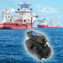
Minnesota company Continental Hydraulics, in partnership with Jet Edge, Inc. and Chukar Waterjet, Inc. developed a solution to help fight the problem. The companyys DO8 valve was used to operate Jet Edgees waterjet pump enabling the jet stream to blast away the hydrate crystals.
The timeliness and schedule was intenseebut we were pleased to deliver a modification to our product capable of withstanding the harsh undersea environment and enormous water pressure at a depth in excess of 5,000 feet,, said Continental Hydraulics general manager Jeff Brandt.
Jet Edgees custom engineered waterjet intensifier pump was dropped into the sea to power a robot-operated waterjetting lancee eliminating the hydrates. This equipment is the first-known waterjet system capable of operating in water depths in excess of 5,000 feet, opening a new frontier for waterjet technology.
Chukar Waterjet, Inc. general manager Bruce Kivisto said, We worried about 2300 pounds of force and the harsh exposure to that valve. Continental Hydraulics recognized the importance, the challenge and delivered a critical component to our success..
Kivisto provided onsite application and engineering services throughout the project, recently returning from several weeks aboard a boat just 50 yards away from the Discoverer Enterprise. He says the solution appears to be working and will continually be monitored.
For more information, visit www.continentalhydraulics.com.
|
|
How Long Should Hydraulic Hose Last?
 By Jack Weeks
GPM Hydraulic Consulting, Inc.
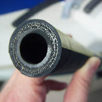
How long should the hoses in a hydraulic machine last? Well, the short answer is that it depends. Some people are surprised to find that hose material has a shelf life and that it can be affected by factors such as temperature, humidity and ultraviolet light exposure of the area where it is stored. This differs by hose type and manufacturer of course, but that is not what our customers usually mean when they ask about hose life. When a hose is replaced on a hydraulic machine, we would like to know about how long we can reasonably expect this hose to stay in service.
Unfortunately, hose life can be very hard to predict. There are simply too many variables between machines to make any sort of blanket statement. But if you find yourself changing the same hose over and over again while the other hoses on the machine seem to be immortal, it is definitely time for some further investigation to determine what deteriorating factors are affecting that particular hose and not the others.
Naturally hoses will not last forever. And certainly they will not last as long as hard pipe. Wherever possible, long hose runs should always be replaced by hard pipe, terminating with a length of flexible hose into.components to absorb shock. But some applications demand hoses and we would like for them to last as long as possible. So even if we can't predict hose life with any accuracy, we can at least be sure that we get the maximum possible life from the hose. Here are a few of the most common mistakes we find that can shorten hose life expectancy:
Using the wrong size hose. Sizing the hose is more than cutting it to the right length and putting on the right fitting. Hoses are designed for specific flow rates, pressures and temperatures. If we deviate from their specifications, hose life can suffer. While that statement may appear blatantly obvious, we often find that hose specifications have been ignored - sometimes inadvertently and sometimes deliberately. Most plants stock hose in various diameters but not of different characteristics. Sometimes this one-size-fits-all approach gets us in trouble, particularly when a new machine is installed that requires hose with different specs. The same hose that is used everywhere else in the plant eventually gets used on this new machine with disastrous results. Since there is only one type of hose in stock, no one is likely to check to see if it suits the needs of the machine - it has to, that's the only one we have!
Sometimes the wrong hose is deliberately installed. We have seen hose that is too small in diameter installed in an attempt to make the machine run faster. A common misconception is that smaller diameter hose results in a higher flow rate. Higher flow rate, of course, does increase speed. The problem with this plan is that a higher flow rate cannot be obtained by undersizing pipes or hoses. Hose diameter affects fluid velocity, not flow rate. No matter how small the hose, if you put 10 GPM into it, you can get no more than 10 GPM out of it. Increasing the velocity will however add heat and turbulence to the machine. Not only will this damage the inner metal tube (especially at bends), it can also cause premature failure of hydraulic components in the machine. At one plant, the technician was so insistent that we were incorrect about this that he timed the movement of the actuators in the machine. They did in fact move faster than they had with the correct larger hose. Only once we pointed out that the system temperature had increased by 37oF did he understand the real reason the speed had increased. He could have had exactly the same speed increase (without the additional turbulence) by turning up his oil heater. Yet he was horrified at the suggestion of doing this! As well he should be - whenever the speed of a machine can be increased by raising oil temperature, there is an orifice that can be opened instead. But that's a different article.
Some people over size hoses as well. This in an an attempt to keep fluid velocity and temperature at a minimum. There is merit to this, but also a point of diminishing returns. As long as your hose meets the requirements of the system, you will probably not get enough benefit to justify the cost of the larger hose. Add to that the problem of making a larger hose fit the application, causing bends at the fitting and increasing the chance of the hose rubbing on another surface or another hose and suddenly oversizing our hoses no longer sounds like such a great idea.
Often hoses are cut too long for the application. When we replace a single hose, we want to be sure we have enough hose so we only have to do it once. So the tendency is to cut the hose longer than we need. Thus hoses tend to "grow" over a period of time. In our hydraulic classes, we teach that most hoses (with exceptions of course, such as traveling cylinders) should be no longer than about four feet. But this is not set in stone - by and large, a little common sense can prevail here. Most of the time, if a hose installation looks good, it is good. But if the hose is rubbing against something, snaking around the floor, has unnecessary bends or is jammed into too small of a space, perhaps it needs some attention.
Failing to take into account the abuse a hose will suffer. Hoses are not indestructible. They should not be installed in such a manner as they are likely to be stood on, run over by a forklift or rub against another hose or surface. If subjection of a hose to a hazard is unavoidable, there are many options available to protect it. If a hose must be installed close to a heat source, for instance, a metal heat shield should be installed to protect it. If abrasion cannot be avoided, use a protective cover. Ultraviolet rays from the sun can badly degrade hose material, so if it must be subjected to the elements, protect it.
Just as water and other contaminants in hydraulic oil can damage components, so can they damage hoses. And whenever we have a choice between installing a hose to run vertically or horizontally, the horizontal installation will cause less pull on the hose fittings.
Forgetting about shock spikes when specifying hose. All too often, we have seen hoses installed that are underrated. A machine that operates at 1500 PSI should not have hose rated for only 2000 PSI. It is not uncommon at all for shock spikes to reach several thousand PSI above the operating pressure of a machine. The OEM can recommend the proper hose pressure rating. And if we use the OEM recommended hose, be sure we set the system pressures to the OEM recommendation as well. A pressure setting that is 200 PSI too high will result in shock spike increases of much more than that. Keep shock spikes to a minimum by making sure the pressures are set correctly and keeping components that absorb shock in good repair.
Using an incompatible hydraulic oil. All hydraulic oil is not the same. A wide range of additives is available. Before trying a new oil, be sure to ask your oil vendor if it could damage the hoses.
Neglect. An inspection of all of the hoses should be performed at least monthly. Signs that a hose is about to fail such as bubbling of the outer hose, loss of flexibility, cracks, discoloration or signs of abrasion are easy to spot. It is always better to replace the hose before it fails. If the hose fails during production, not only will production time be lost but it is likely that the ruptured hose will damage something else. Anyone who has ever witnessed a hydraulic hose breaking knows that it is not something to be taken lightly. Tremendous force is released (and a lot of hot hydraulic oil). If your hoses have lasted a year or two, consider yourself fortunate and replace them whether they appear to need it or not. And if a hose is located where someone could be injured or killed if it fails, a much closer change interval is justified.
Jack Weeks entered GPMMs organization in January of 1997 as a CAD draftsman and hydraulic instructor. He has trained thousands of electricians and mechanics in Hydraulic Troubleshooting methods. His computerized animations have made GPM's presentations and training CD's the recognized leader in the industry. He received his education from the Georgia Institute of Technology School of Electrical Engineering and the Department of State Foreign Service Institute. Jack is an experienced draftsman and taught telecommunications equipment operation and repair for the Central Intelligence Agency at American embassies overseas.
GPM Hydraulic Consulting, Inc.
Box 1376
Monroe, GA 30655
(770) 267-3787
www.gpmhydraulic.com
|
|
Fuel Consumption Up? Perhaps Your Hydraulic Fluid Is To Blame.
 Chiropractors say that problems with the 6T vertebra nerves affect the stomach and can include heartburn, nervousness and indigestion. How is that possible? How can your spine be related to your stomach? We all know that the foot bone is connected to the leg bone and the leg bone is connected to the knee bone, but your spine to your stomach, really?
This example is surprisingly similar to hydraulic systems. Herees how. Just like the human body, a hydraulic system is a complex structure comprised of integrated components. These components are interconnected, relying on each other to perform very important tasks, and if a problem exists in one area it can be due to an issue or complication in another. Fuel consumption is a great example it has a direct correlation to energy efficiency and hydraulic fluid performance.
Fuel Consumption
With todayys fuel costs, it behooves you to really examine your fuel consumption and to take measures to protect your bottom line. Operating costs associated with fuel consumption are substantial. Hydraulic systems are becoming smaller resulting in the fluid running at higher temperatures. The systems have to work harder to maintain a constant pressure in the hydraulic pump, therefore they require more energy and fuel to provide the same output. But relax, there is a way to significantly improve your fuel consumption without sacrificing productivity and performance: upgrade your hydraulic fluid.
Take A Close Look
Mediocre hydraulic fluid can be a contributing culprit to increased fuel consumption. How is your fluid performing? Perhaps itts not maintaining optimal fluid viscosity. Maybe itts hindering system performance. Is it one of the root causes for your fuel consumption woes? If so, then itts definitely time to switch to a higher quality multigrade hydraulic fluid one that can provide pump and energy efficiencies.
Can It Handle The Heat?
Viscosity is the most important factor when selecting a hydraulic fluid and itts imperative that you select the grade based on the systemms temperature operating window (TOW). Also remember that a typical hydraulic pump converts approximately 20% of its horsepower into heat, therefore most fluids run at elevated temperatures. A hydraulic fluid that maintains optimum viscosity at these higher temperatures will maximize hydraulic pump efficiency.
Hydraulic Pump Efficiency
Maximizing hydraulic pump efficiency is achieved by having optimal fluid viscosity and by resisting changes in viscosity throughout wide temperature changes and over time. Your hydraulic fluid must be able to provide an ideal balance between mechanical efficiency and volumetric efficiency.
Simply put: the viscosity of the hydraulic fluid must be thin enough for the pump to start easily, especially at low temperatures, and to prevent it from working too hard (mechanical efficiency), but be thick enough to prevent internal pump leakage, loss of pressure and provide effective lubrication (volumetric efficiency).
How Much Fuel Can Be Saved?
A case study (see figure 1) was conducted to show you just how much fuel could be saved simply by using an energy efficient hydraulic fluid. The case study was based on a medium-sized excavator with dual piston pump feeding three piston motors (running at 90% throttle).
Figure 1. Fuel Savings Results
Example:
Oil Drain Interval (hours): 4,000
Hydraulic Fluid Volume (L): 255
Fuel Consumed (L): 89,000
Fuel Costs ($/L): $1.00
Total Fuel Cost**: $89,000
Petro-Canadaas HYDREX MV is 2.3% more energy efficient than the leading global competitor achieve fuel cost savings of + $2,000.
** Notes:
The efficiency of the hydraulic pump is based on viscometric properties of the fluid at certain pressure and temperature conditions.
Results of the Case Study were extrapolated to 4,000 hours using Denison T6CM pump (B10 cartridge 2000 rpm, 200 bar, 700C/1588F) based on benchmarking data for HYDREX MV 36 vs. the leading global competitor.
Fuel costs ($/L) can fluctuate based on market conditions.
See, the energy efficiency battle can be won! When used in conjunction with integrated maintenance protocol, a higher quality hydraulic fluid can help increase pump efficiency, lower your diesel fuel consumption and CO2 emissions, increase equipment productivity, and more. Not to mention that the cost of fuel is a substantial expense relative to the cost of your hydraulic oil.
Good news for those of you experiencing nervousness and indigestion maybe it isnnt your 6T vertebra after all. Maybe the stress caused by an underperforming hydraulic fluid is to blame. You should really get that checked out.
- By Jennifer Lai
For more information on Petro-Canadaas line of hydraulic fluids, please call 1-800-268-5850, e-mail lubecsr@petro-canada.ca or visit www.lubricants.petro-canada.ca.
|
|
Intelligent Hydraulic Axis Increases Sawing Performance
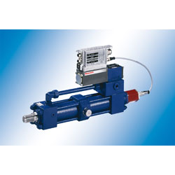 Intelligent Hydraulic Axis Increases Sawing Performance:
Integrated Axis Controllers IAC-R from Rexroth
With dynamic, precisely positioning and compact, integrated hydraulic axis controllers IAC-R for sawing technology, Rexroth opens up significant potential to improve the sawmill output with increased material throughput and higher accuracy. Compact drive units with integrated control electronics and position measuring systems control the dynamic cutting width adjustment on disk saws in a decentralized way or assume highly precise positioning tasks on sawing lines. The complete, ready-to-install axis communicates with all commercial field buses and combines the high power density and ruggedness of hydraulics with the efficiency of modern motion controls.
The electronics integrated in the IAC-R high-response control valves internally stores all axis-specific product parameters, which can vary during operation, and works them off independently of the cycle time of the higher-level control. This increases the dynamics of the saw blade adjustment and simplifies the modularization of sawing lines. The reduced wiring effort for the compact axes in conjunction with programming and parameterization software, which can be intuitively operated, shorten commissioning times.
Rexroth rated the complete drive unit for the harsh operating conditions in sawmills: Direct mounting of the IAC-R valve onto the cylinder results in a high load stiffness of the drive. The contact-free position measuring system integrated in the cylinder is prepared for the extreme operating conditions in the wood processing sector, such as shock loads and severe contamination by wood dust. Even in the event of a supply voltage failure or a machine restart, the absolute position measuring system precisely signals the current position to the axis controller without requiring referencing.
In the case of a fault, the IAC-R issues a diagnosis message via the field bus to the higher-level control. This simplifies fast localization and elimination of the fault. Since stored axis parameters can simply be copied to replacement valves,
the axes are fully reproducible and the machine availability is increased also when servicing is required. Moreover, if a fault occurs, a field bus signal causes the high-response control valve to move to a failsafe position, which guarantees a safe standstill of the axis and hence protection of the operator.
Bosch Rexroth Canada is the Canadian partner company of Bosch Rexroth AG, one of the worldds leading specialists in the field of drive and control technologies. Under the brand name of Rexroth the company supplies more than 500,000 customers with tailored solutions for driving, controlling and moving machinery used in industrial and factory automation as well as in mobile applications. As The Drive & Control Company, Bosch Rexroth develops, produces and sells components and systems in more than 80 countries. In 2007 Bosch Rexroth AG, part of the Bosch Group, achieved sales of about 5.4 billion Euro with approximately 33,000 employees.
Bosch Rexroth Canada
3426 Mainway Drive
Burlington, ON
Canada L7M 1A8
Telephone (905) 335-5511
Fax (905) 335 4184
|
|
Rexroth Hydrostatic Regenerative Braking System
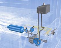 Rexroth Hydrostatic Regenerative Braking System (HRB) Makes Commercial Vehicles Up to 25 Percent More Economical
Rexroth hydrostatic regenerative braking system (HRB) reduces fuel consumption by up to 25 percent and can be retrofitted as an add-on system even in vehicles without hydraulics.
Hydrostatic regenerative braking system (HRB) stores brake energy in a hydraulic pressure reservoir and relieves the load on the main drive when the vehicle is accelerating potentially reducing fuel consumption by up to 25 percent.
(Bethlehem, PA - www.boschrexroth-us.com) Bosch Rexrothhs hydrostatic regenerative braking (HRB) system includes a hydrostatic hybrid drive which uses the considerably higher performance of hydraulics compared with available batteries to substantially reduce fuel consumption even in heavy commercial vehicles.
When the driver presses the brake pedal, a hydraulic unit integrated in the drivetrain presses the hydraulic fluid into a high-pressure reservoir. The resulting resistance makes the vehicle decelerate. When accelerating, the hydraulic pressure reservoir is controlled electronically to release the pressure and it relieves the load on the diesel engine. As a result, the engine consumes less fuel, generates less exhaust gases, and functions more quietly.
The compact Rexroth HRB is ideal for use in various commercial vehicles. The HRB can be integrated and even retrofitted in the chassis as an add-on system, without major modifications.
The system reduces fuel consumption by up to 25 percent in vehicles used for very short distances such as urban buses, garbage trucks, fork lift trucks, or delivery vehicles driven in city traffic. Fuel consumption can also be reduced considerably in other commercial vehicles and trucks used for intercity service.
Each time a driver brakes, the HRB system stores energy which would otherwise be lost. The hydrostatic hybrid drive functions almost maintenance-free and wear-free compared with electric hybrid drives. For example, it is not necessary to regularly change the battery. In addition, the HRB also improves the acceleration of the vehicle. The additional drive energy allows vehicles to be equipped with smaller diesel engines and therefore further reduce fuel consumption and emissions.
All Rexroth HRB components are based on standard components from the manufacturer's current product portfolio. Prototypes of the Rexroth hydrostatic hybrid drive are currently being tested in on-road vehicles.
|
|
Recipe for Success for Plastics Processing Applications
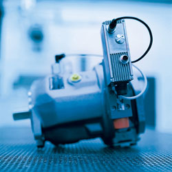 Short cycle times and reliable, high repeatability are top requirements of manufacturers of plastics processing machines. Bosch Rexroth meets this requirement with the SY.DFE, an electro-hydraulic closed-loop control system with 100,000 units installed worldwide. The SY.DFE uses a variable displacement axial piston pump for controlling pressure, displacement and power without throttling losses in the power branch.
The SY.DFE provides the ultimate in hydraulic energy efficiency, electronically controlling both flow and pressure with exceptional speed and precision. A proven combination of a variable displacement axial piston pump of swashplate design and innovative proportional control electronics, the SY.DFE provides efficient, reliable controlling of the pump.
The SY.DFE was launched at the plastics processing trade fair in DDsseldorf in 1989, and with 100,000 units installed, it demonstrates the exceptional value it has provided in multiple plastics processing applications since its debut. Primarily used in injection molding machines, the system is based on a Rexroth A10VSO or A4VSO axial piston pump. By adjusting the pumpps swashplate, flow and pressure can be infinitely varied, and the required flow and pressure can be generated fast and accurately for specific machine functions.
In addition, functional sequences in an injection-molding machine can be precisely controlled with the help of the SY.DFE. The flow control works without pressure losses in the power branch, which significantly increases the hydraulic efficiency within the machine. Moreover, the total efficiency of the machine is increased due to the high repeatability of the control.
Rexroth offers this system in three versions: SYDFE1 with external closed-loop control electronics, the SYDFEE, with analog, integrated functions, and the SYDFEC, which offers integrated, digital closed-loop control electronics and the optional field bus controlling via CAN, so that users in the plastics processing industry can benefit from a proven plug-and-play system.
Bosch Rexroth Canada is the Canadian partner company of Bosch Rexroth AG, the worldwide leader in Drive & Controll. Under the brand name of Rexroth the company supplies more than 500,000 customers with tailored solutions for driving, controlling and moving machinery used in industrial and factory automation as well as in mobile applications. As The Drive & Control Company, Bosch Rexroth develops, produces and sells components and systems in more than 80 countries. In 2006 the company of the Bosch Group achieved sales of approximately 4.9 billion Euro with more than 29,800 employees.
Company Information:
Bosch Rexroth Canada
Ontario, CANADA
www.boschrexroth.ca
info@boschrexroth.ca
|
|
The Case for Safety Catchers
 Ken Davis, Business Development Manager, Advanced Machine & Engineering Co.
The Europeans have the answer to safeguarding hydraulic and pneumatic presses from catastrophic failure. The good news: now itts available here in the U.S.
An ounce of prevention is worth a pound of cureethe old adage rings especially true for the thousands of press operators today trying to reduce their production costs and stay competitive with higher speeds, smaller batches and keep your fingers crossed greater machine uptime. The cost today for a catastrophic press failure? On the low end, certainly thousands of dollars in lost production time and die replacement costs. On the high end, the loss of a key operator due to injury or a customer that takes his business elsewhere rather than run the risk of falling behind schedule again.
Sure, todays most modern hydraulic and pneumatic presses have a variety of OSHA mandated protection systems in place to ensure operator safety. Guards, interlocks, electro-sensitive and opto-electronic devices, emergency stop devices and other redundant systems have helped make presses safer in recent years. But when it comes to safeguarding the presses themselves from expensive damage to the press or dies, standards in the U.S. fall well short of their European CEN counterpart, which states in prEN 693 Machine tools Safety Hydraulic Presses: Where there is a riskkfrom a gravity fall of the slide /ram a mechanical restraint device, e.g. a scotch, shall be provided to be inserted in the presssOn presses with an opening stroke length of more than 500 mm and a depth of table of more than 800 mm, the device shall be permanently fixed and integrated with the press. A similar CSA Standard (Z142-02) exists in Canada
Faulty vs. failsafee. For most American press operators, however, a ratchet bar, locking bolt or latch is all thatts standing between them and a catastrophic crash should hydraulic or pneumatic pressure be lost suddenly or the lifting mechanism experience a mechanical breakage. When functioning properly, the ratchet system -- usually running the length of the press stroke-- does an adequate job of arresting the fall of the ram and preventing a catastrophic crash. A spring latch will automatically extend to engage the teeth of the ratchet at some point before a crash can occur. Unfortunately, the ratchet is a wear part that after hundreds, even thousands of press cycles can begin to exhibit signs of wear that are difficult to detect visually, and probably cannt be heard, by even the most experienced operator. Over time, the ratchet teeth, spring and latch typically begin to wear, since the spring latch makes contact with the teeth (but doesnnt engage) on the upstroke of the ram every time the ram is raised for the next part. The ratchet, and even the end of the spring latch, can wear to the point where a fall cannt be prevented.
In addition, locking bolts and latches often operate only at the top of the stroke, and ratchet bars at fixed interval positions. Consequently, the ram must often be retracted to its full stroke position each and every part, despite the fact that the part requires only a short opening stroke. This can add considerable, and very expensive, non-productive time to the cycle.
But in Europe, Canada and elsewhere in the world, most presses are equipped with a SITEMA Safety Catcher, which satisfies the requirements of CEN and CSA safety standards, foolproofs presses from a catastrophic crash, and allows the operator to optimize the stroke for any size part. The SITEMA Safety Catcher works a little like the Chinese Finger Trapp you probably played with as a child. You could easily put your finger in one end of the paper cylinder, but it was very difficult to retract it. In fact, the harder you pulled the more clamping power the simple paper cylinder seemed to exert on your finger. The SITEMA Safety Catcher works in similar fashion. If hydraulic or pneumatic system pressure fails, or if a rope, chain, belt or toothed drive breaks, the SITEMA Safety Catcher prevents the load from crashing down at any position of the descent. Better yet, the system is self-intensifyingg, so that as downward force increases, so too does the Safety Catcherrs clamping force.
Herees how it works (see Fig. 2 and 3):
1) A cylinder rod is mounted to the top of the platen extending through the press crown and the Sitema safety catcher housing (Figure 2). The safety catcher housing is securely fixed to the machine crown / frame and surrounds the rod which is free to move during normal operation. Wedge shaped clamping jaws inside the housing are held with hydraulic or pneumatic pressure to keep the wedges in position so that the rod can move freely.
2) This Safety Catcher instantly becomes effective when hydraulic or pneumatic pressure is lost or released. A spring causes the clamping jaws to firmly contact the rod. As a result, any downward movement of the rod initiates the self-intensificationn feature securing the load.
3) Significantly, the energy of the falling or sinking load is used to apply additional clamping force if needed. In other words, self-intensifyingg friction created between the clamping jaws and the cylinder rod draws the jaws into their maximum clamping position after only a few millimeters of movement.
4) If the load continues to increase, the Safety Catcher will continue to hold the rod in a fixed position until a pre-determined static holding force limit is exceeded (approximately 3-4 times the retain force). Beyond that point, the Safety Catcher continues to safely hold the rod, with a braking action dissipating the kinetic energy of the falling mass while it continues to resist the downward movement of the platen.
5) Only when hydraulic or pneumatic pressure is restored in conjuction with the equivalent reverse movement of the rod are the clamping wedges released, making the SITEMA Safety Catcher inherently failsafe.
SITEMA is catching onn everywhere. From presses to large hydraulic elevators to stack loaders to machine tools in almost any application where a large load is traveling and the potential for a catastrophic mechanical failure exists SITEMA Safety Catchers have been applied successfully and in increasing numbers, as safety standards toughen around the world. They are available in a variety of sizes to meet most common press sizes, including the very largest. Most importantly, they are readily available today in the United States through Advanced Machine and Engineering Co.
About AME
AME is a global manufacturer and distributor of precision machine components, fluid power components, fixturing/workholding, power drawbar and spindle interface components, and saw machines and blades. The company also designs and builds special machines for a variety of industries, and provides machine rebuilding, retrofitting and contract manufacturing services. AME has partners and customers around the world and across the U.S. To learn more, visit www.ame.com.
|
|

